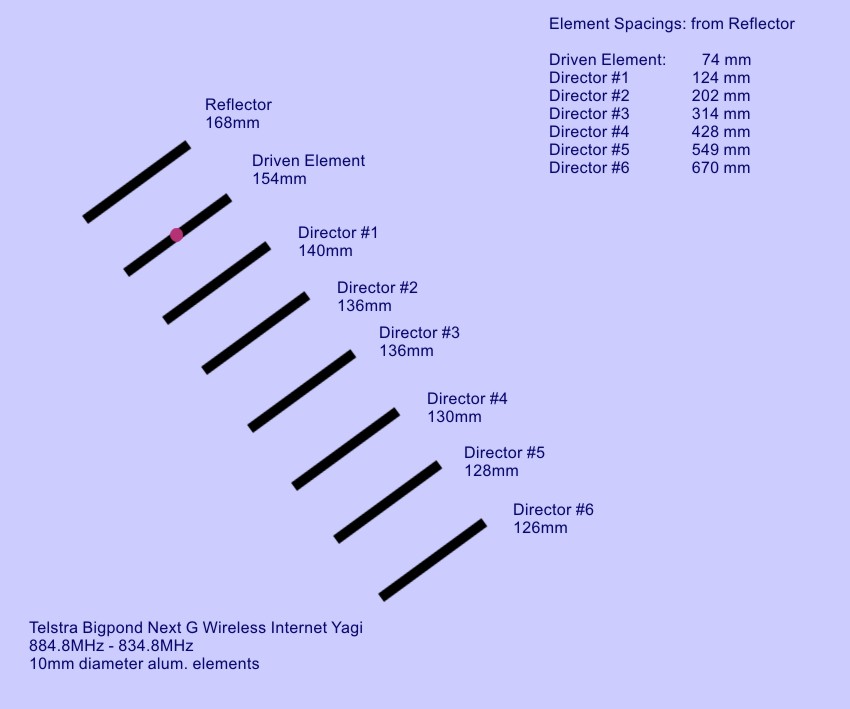
This antenna was made for Telstra Bigpond Next G Wireless Internet
which used two frequencies: uplink 839.8MHz and downlink 884.8MHz
[Referred to in Australia as "Telstra 3G 850MHz"].
Researching transmission towers for Telstra frequencies in different
areas... this is frequency to search for.
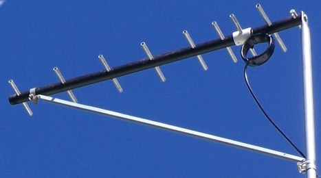
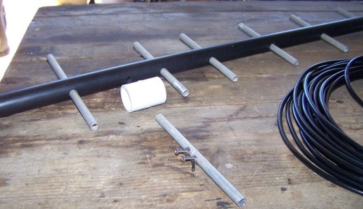
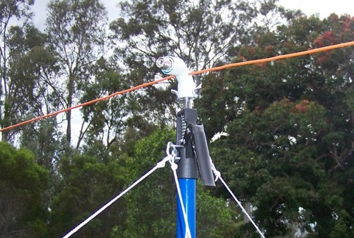
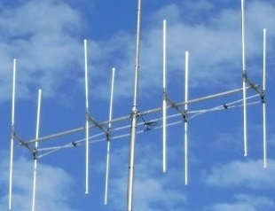
Finished antenna
Materials and making a start:
First the Boom I wanted light, rigid and preferably
non-metal and found a thick-walled black plastic pipe (called a
'riser'), in the hardware story gardening section. Both ends are
threaded as they're used for attaching taps. This riser is 900mm
and the final antenna will be around 700mm - cost is about $6.
From the plumbing section I got a straight PVC joiner which fit
over the riser - costs about $2.
Get 2 stainless 3mm bolts, long enough to go through your 10mm
alum tubing, (excess length won't matter). 2 washers to suit,
and 2 small lugs to solder to the coax tails.
Elements are 10mm aluminium tube - you need just under 1200mm of
aluminium tubing.
Cut all 8 elements at the lengths shown - mark the D.E. and put
it aside till later.
Measuring left side of one element to left side of the next
will maintain the C to C relationship
Measurements begin from the Reflector (the Back element) and
each hole placement measurement is taken from that point
Note the "Element Spacings from Reflector" measurements in the
specs image above
10mm Aluminium Tubing was used
12mm can be used with the same measurements without altering
antenna characteristics
Construction Process
Step By Step Build
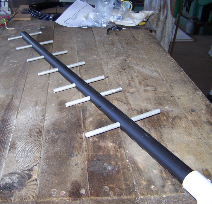
8 holes in the boom at the specified distances 7
Elements fitted Hole drilled ready for Driven Element
Drill all 8 holes in the black plastic boom at the correct
distances, and fit SEVEN elements - Don't fit the D.E. Yet!
The last hole (Director #6) should be out near the end of the
boom, leaving excess at the back, behind the Reflector.
This excess provides a mounting point for a brace onto a mast.
End of the boom was stuffed with lightweight styrene and a blob
of silicone, as a seal against rain and bugs.
Do Not fit the Driven Element at this stage.
The elements should be a tight, secure fit or glue in place if
necessary.
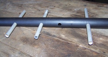
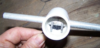
A visual clue about where Driven Element will Fit
Note 2 bolts sitting in the holes in the aluminium to assist
your construction
Later you will cut the boom & place the
White PVC joiner into the boom.
The Driven Element was cut at 154mm long, then cut in half.
There is short pencil inside the aluminium 'halves' to keep them
about 1mm apart.
Pre-drill 2 small (3mm) holes through the Driven Element quite
close to the ends - coax will attach here.
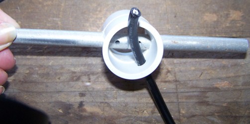
Drill 3 holes in white PVC
3 holes are drilled in the PVC. 1 hole thru centre, 10mm
or diameter of D.E. material being used.
1 hole off-centre, the diameter of Coax. It's a tight space so
drilling the coax hole off-centre will aid attaching coax.
Pull coax through so tails [ends], can be prepared.
Prepare Coax End by making tails
Make tails by removing 25mm of outer black plastic. Extract the
outer mesh braid and twist into a single thick tail.
Remove some inner plastic dielectric, expose the centre wires.
Twist into single thin tail.
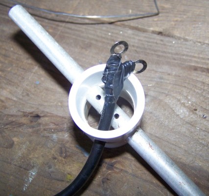
Keep tails short as possible - tin & solder a ring terminal onto
each tail end.
Images shows insulation tape covering to ensure 2 terminals can
be screwed into the D.E. without touching.
1 tail must be longer than the other due to the angle of coax.
Secure ring terminals to D.E. using 3mm bolts
Bolt the ring terminals onto the D.E. (this is why pre-drilling
holes earlier).
A long skinny screwdriver will be needed to fit 3mm stainless
bolts & washers. To prevent the coax kinking, slowly withdraw
the coax back out of the PVC joiner, while screwing the bolts
down onto to the D.E.
Test the coax continuity to ensure no short circuit from all the
pulling & twisting.
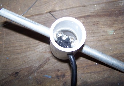
View of PVC Joiner from the rear
The 3mm stainless bolts could have been shorter but so long as
the boom will fit around them, it's OK.
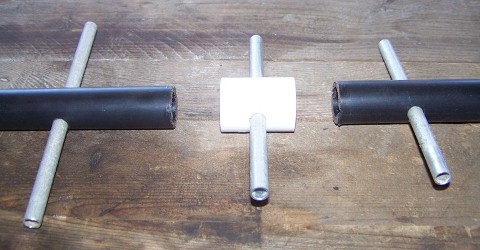
Almost finished
Cut the Boom
Cut through the centre of the hole that was drilled for the
D.E. earlier
Cut through the boom and pre-fit the ends of the black riser
into the PVC joiner.
Before gluing in place double check the dimensions! Ensure the
D.E. is at the correct spacing now that it is contained in the
PVC.
If measurements aren't correct shave small amounts off the ends
of the black riser, try the fit again, repeat until you have the
correct dimensions.
The dimensions are critical, so take the time to test at this
point.
The distance between Reflector & D.E., when it's assembled,
must be 74mm.
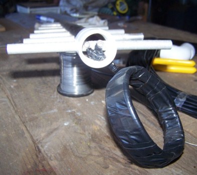
View with the front section of boom attached
The 'roll' in the image is an 'ugly balun' - 6 turns of coax
taped together.
The BALUN avoids interference from short lengths of
exposed/unshielded coax at the Driven Element.
I use flexible RG58 CellFoam low loss coax which suits my balun.
Buy what you can afford but understand that you get what you pay
for.
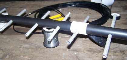
When the rear section of the boom, which has the reflector, is
glued into place the antenna is complete.
As mentioned above, be prepared to shave away small amounts of
the boom so the ends fit inside the PVC and maintain those
correct dimensions. An additional small piece will be 'nibbled'
out until the coax can pass out of the PVC and exit the boom.
Repeating once more...Check specifications throughout the build
to ensure your distances are accurate.
More Info...
Finish the Job
The final stage of mounting will vary with every assembly. The aim
is to get it into the air, at a comfortable height for each build,
stabilized and pointing towards the signal.
The material behind the Reflector can be any length, it has no
bearing on the antenna design and provides mounting and bracing
points.
Polarisation
This may take a leap of faith as all the experts will tell you
that Next G technology is a vertically polarised medium and
hence they say you should make vertical antennas.
Research YOUR nearest transmission tower & you will discover
that some are Vertical and many are SLANT polarisation.
Research on Whirlpool.net.au is helpful as people build and test
antennas and compare results... proving that if your Telcos
transmission tower is SLANT polarisation - you will get better
download speed from a Horizontally polarised yagi.
Conversly if your nearest 850MHz transmission tower is Vertical
- then you stick with Vertical polarisation too.
Performance
What about the signal-strength lights and bars on your modem?
The number of bars is simply an indication of the noise in the
air that the modem can see/hear. It is NOT a true indication of
the directional gain you're achieving with your yagi. (I could
prove this to you with lots of testing equipment but that would
bore you).
A well-built antenna filters out all the noise and you'll only
be seeing the signal you're looking for so 2 bars/lights might
be great speed.
I'm not an expert by any means but I research propagation
continually, and I can build an antenna to achieve the results I
want - and at home handyman prices and that's good enough for
me.
I hope this project has been of some help to you.
Important update 2020
Telstra Australia has published the following:
" Telstra will be switching off 3G in 2024. Before switch off,
you can use handsets supporting 3G on 850MHz... After switch off
you will still be able to access the Telstra Network on 700MHz."
Find out more at:
Telstra 3G is Closing
3G telecommunications is being retired in Australia in 2024
but I will leave this page live on the internet
The 3G mode [and 850MHz frequency] is still used in other
parts of the world
As you see in the
FAQ/Gallery Page
people from several countries sent feedback regarding their
build and how they use this antenna for their local
conditions.
With contacts from remote USA, Colombia & Philippines, people
are building this antenna to suit local conditionss. So it is
still a relevant resource.
I even had enquiries from Africa on how to use it to track
lions (with their safety collar transmitters).
It is still a relevant resource
Personal Projects
Never stop learning, sharing knowledge or travelling
Each of these images will link to a dedicated webage where I share
my Amateur Radio projects or travel pages.